
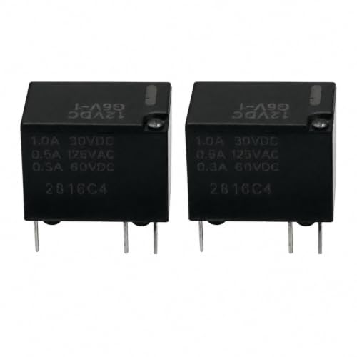
G5V-1 12VDC Signal Relay 2-Pack SPDT 1-Form-C 5-Pin 1A 30VDC PCB Through-Hole Mount Subminiature Sealed Industrial Replacement for Control Panel Switching Multi-Purpose
Product Description
G5V-1 12VDC Signal Relay 2-Pack SPDT 1-Form-C 5-Pin 1A 30VDC PCB Through-Hole Mount Subminiature Sealed Industrial Replacement for Control Panel Switching Multi-Purpose
- [PART NUMBER + SPECS CHECK] G5V-1 subminiature 5-pin SPDT (1 Form C) electromagnetic PCB signal relay with 12 VDC coil. Standard printed contact rating: 1A at 30 VDC, 0.5A at 125 VAC, 0.3A at 60 VDC (resistive loads). Confirm the printed part designation G5V-1 and the 12 VDC coil variant before ordering. Verify coil voltage (12 VDC), contact form (SPDT 1 Form C), pin count (5-pin), and through-hole PCB layout match your application before installation. Compatible form factor: Industry-standard subminiature 5-pin SPDT through-hole PCB signal relay in the matching 15.5 x 10.5 x 11.5 mm enclosed footprint.
- [FUNCTION + CIRCUIT POSITION] Single Pole Double Throw (SPDT, 1 Form C) electromagnetic signal switching relay designed for low-signal PCB switching. Typical uses: low-voltage signal routing, instrumentation signal switching, A/V equipment control logic, security alarm panel relays, access control relays, intercom and doorbell control, hobby and DIY maker PCBs, industrial control panel signal switching, PLC output relay replacement, test and measurement equipment, scientific lab instrument relay replacement, telecom control board relays, computer peripheral signal routing, low-power DC polarity switching,
- [ELECTRICAL SPECIFICATIONS] Coil: 12 VDC nominal | 880 Ohm +/-10% coil resistance | Approx. 13.6 mA nominal coil current | Approx. 150 mW (0.15 W) coil power. Must operate at 70% of rated (8.4 VDC max) | Must release at 10% of rated (1.2 VDC min) | Max permissible 130% of rated (15.6 VDC max) at 23 deg C. Contacts (resistive): 1A at 30 VDC, 0.5A at 125 VAC, 0.3A at 60 VDC. Operate time Approx. 5 ms | Release time Approx. 5 ms. Insulation resistance 100 MOhm min at 500 VDC. Dielectric strength: 1,000 VAC for 1 min between coil and contacts; 500 VAC between open contacts. Confirm all electrical parameters match your drive circuit before installation.
- [MECHANICAL & BUILD QUALITY] Sealed plastic enclosure with flux-protection construction, flame-retardant grade housing, Silver Alloy (Cadmium-Free, Ag-Alloy) contact material for low contact resistance and long electrical endurance. Subminiature body footprint - Approx. 15.5 x 10.5 x 11.5 mm (0.61 x 0.41 x 0.45 inch) | Approx. 3.5 g (0.12 oz) per relay each relay. Mechanical operating frequency up to 18,000 operations per hour. Electrical life: 100,000 operations minimum at rated resistive contact load. Vibration resistance: 10 to 55 Hz, 1.5 mm double amplitude. Shock resistance: 1,000 m/s squared (mechanical, approx 100G); 200 m/s squared (functional, approx 20G).
- [PIN CONFIGURATION & TERMINAL DESIGN] 5-terminal subminiature SPDT through-hole PCB layout: 5 round through-hole pins arranged in a single row on the bottom of the housing, designed for direct soldering to a control PCB. Standard pin assignment: Pin 1 = Coil A1, Pin 2 = Common (moves between NC and NO when coil energizes), Pin 3 = Coil A2 (no polarity required on DC coil), Pin 4 = NC (Normally Closed, Common rests here when coil de-energized), Pin 5 = NO (Normally Open, Common connects here when coil energized). Compatible with industry-standard 5-pin SPDT subminiature PCB relay pad layouts. Use a temperature-controlled soldering station; do not overheat the housing.
- [CERTIFICATIONS & SAFETY] Certified to UL Recognized Component standard and CSA Certified component standard - these are independent third-party safety certification marks, not brand names. RoHS-compliant lead-free construction. Creepage distance and dielectric strength ratings conform to UL and CSA insulation standards. Built-in coil suppression is not included - add a flyback diode (1N4148 or 1N4007 or equivalent) across the coil input pins (A1 and A2) for DC-driven transistor or MOSFET circuits to protect driver circuitry from back-EMF voltage spikes. Each relay is individually inspected and tested before packaging.
- [TYPICAL APPLICATIONS] Engineered for: low-voltage signal routing on hobby and maker PCBs, instrumentation signal switching, A/V equipment signal relay replacement, security alarm panel relay logic, access control relay circuits, intercom and doorbell control relays, industrial control panel signal switching, PLC discrete output relay replacement, test and measurement equipment signal routing, scientific lab instrument relay replacement, telecom equipment control board relays, microcontroller-driven relay driver boards, low-voltage lighting control logic relays, automotive aftermarket 12V ECU and fuse box relay repair (matching form factor required),
- [SYMPTOMS + DIAGNOSTIC INDICATORS] A failed subminiature signal relay may produce: stuck active state (Common stays connected to either NC or NO regardless of coil drive), stuck open state (Common does not switch when coil is driven), intermittent switching (Common alternates between NC/NO spontaneously, or only switches under vibration or after multiple drive pulses), high coil current draw without contact actuation (shorted coil winding), no coil current draw at rated voltage (open coil winding), contact welding (Common permanently connects to NO after coil de-energizes), high cold contact resistance (oxidized or worn silver-alloy contacts).
- [INSTALLATION TIPS] Disconnect all power from the host circuit before soldering or replacing the relay. If replacing an existing relay, photograph the as-installed PCB orientation and pin footprint first. Match coil voltage (12 VDC), contact form (SPDT, 1 Form C), and 5-pin through-hole layout before installing. Apply a flyback diode (1N4148 or 1N4007) across the coil input pins (A1 and A2, cathode to the more positive coil pin) for transistor or MOSFET DC-driven circuits to suppress back-EMF voltage spikes. Solder PCB through-hole pins with a temperature-controlled soldering station (310 to 340 deg C, no more than 3 to 4 seconds per pin) - do not overheat the housing.
- [COMPATIBILITY NOTE] Industry series designations, form-factor descriptions, and cross-reference identifiers are used only for compatibility verification. Verify the as-shipped contact rating (1A 30VDC / 0.5A 125VAC / 0.3A 60VDC), pin layout (5-pin SPDT through-hole), coil voltage (12 VDC), and dimensions (Approx. 15.5 x 10.5 x 11.5 mm (0.61 x 0.41 x 0.45 inch)) match the G5V-1 specification before ordering. Confirm the coil voltage variant specified by the part number suffix matches your drive circuit before installation. Part number designations
Technical Specifications
You might also like

Vionic Renee Thong Sandals Black Leather 10 M

Two Country Boys from Mallet: The Miracle of Manglier Tea

Car Cover for Lexus ES200 ES240 ES250 ES260 ES300 ES350 ES500 IS200 IS220 IS250 IS300 IS350 IS500 is-F Waterproof All Weather Add Velvet Outdoor Protect Car Paint

TRUGLO Strut Stopper Xtreme Combo with Gobble Dot Universal Dual Color Turkey Sight, OptimaChoke HP 12 GA

Small Table Lamps Set of 2 for Living Room 20.25" Gold Lamps Bedside Lamps

Men's Pleated Trousers Solid Classic Relaxed Fit Suit Pants for Work Wear

DNA

Clear Cubic Zirconia Drop Wedding Jewelry Set for Bride Women Silver-Tone